Sign up now to join the JEGS email newsletter and be the first to learn about new products, special deals and e-mail only offers!

A tachometer, often referred to as a "tach," is a gauge that measures and displays engine speed in RPMs (revolutions per minute). Understanding engine RPMs is crucial for various purposes, including setting idle speed, diagnosing engine performance issues, defining a rev limit, knowing the engine's redline, determining engine revolutions at specific vehicle speeds, and more. Tachometers receive an electrical pulse signal from sources like the negative side of the ignition coil, the engine's ECM/computer, or an aftermarket ignition control box. They convert this signal into a mechanical or digital display on the gauge face. Most tachometers come with instructions on how to install them, simplifying the assembly process.
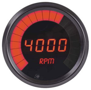
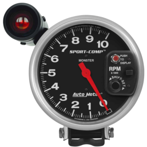
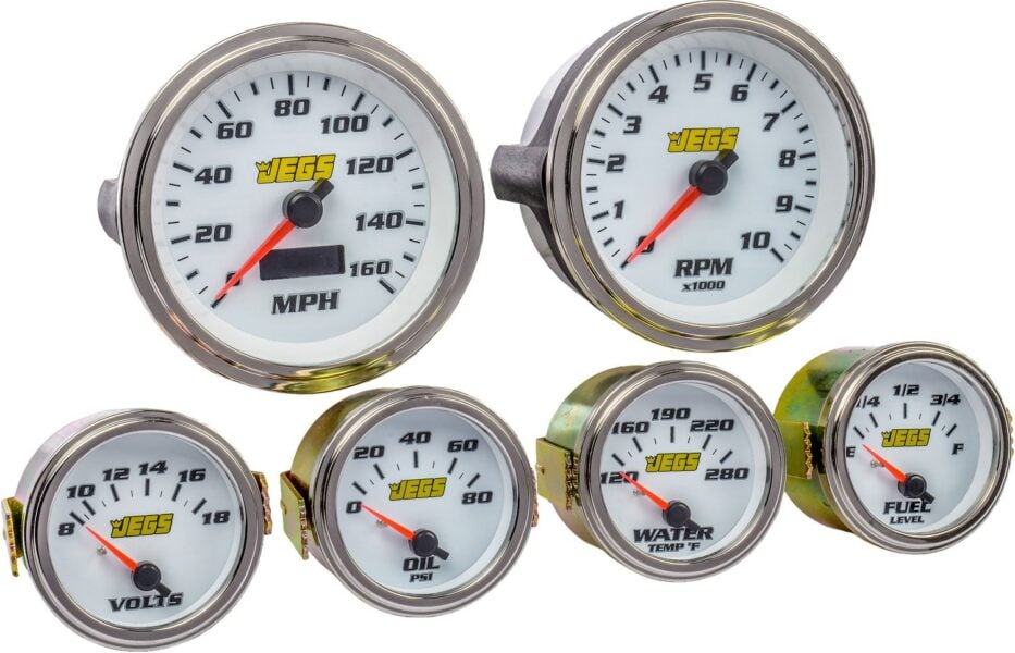
The market offers a variety of tachometers with different features, allowing you to choose one that suits your needs. When selecting a tachometer, consider factors such as size, color, style, compatibility with your engine's number of cylinders, and signal input. Tachometers may also include additional features like a shift light, which activates at a specific RPM you set, and RPM recall, which records the highest RPM achieved until reset for review. Other options are available depending on the brand and style of tachometer.
Gather the Required Materials:
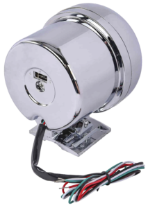
Choose the Mounting Location:
Select a suitable location on your vehicle's dashboard, steering column, or instrument cluster to mount the tachometer. Some people prefer mounting it directly to the hood with a waterproof housing or on the console. Tachometers often come with pedestals that allow for secure bolting or screwing in place, whether on top of or under the dash. Some tachometers are designed to mount directly into the dash through a pre-cut hole.
Ensure that the chosen location provides clear visibility while driving and does not obstruct essential gauges or controls.
Prepare the Mounting Surface:
Thoroughly clean the mounting surface to remove dirt, debris, or grease.
Use a template provided with the tachometer to mark the mounting holes if necessary.
Install the Mounting Bracket (if applicable):
Follow the manufacturer's instructions to install the mounting bracket securely to the surface.
Use provided screws or hardware to fasten the bracket in place.
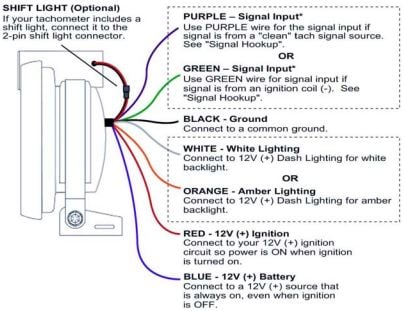
Connect the Wiring:
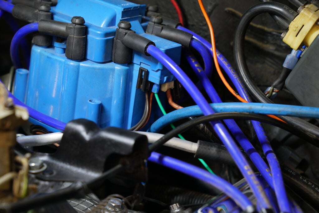
Refer to the wiring diagram or instructions provided with the tachometer and consult your vehicle's wiring diagram.
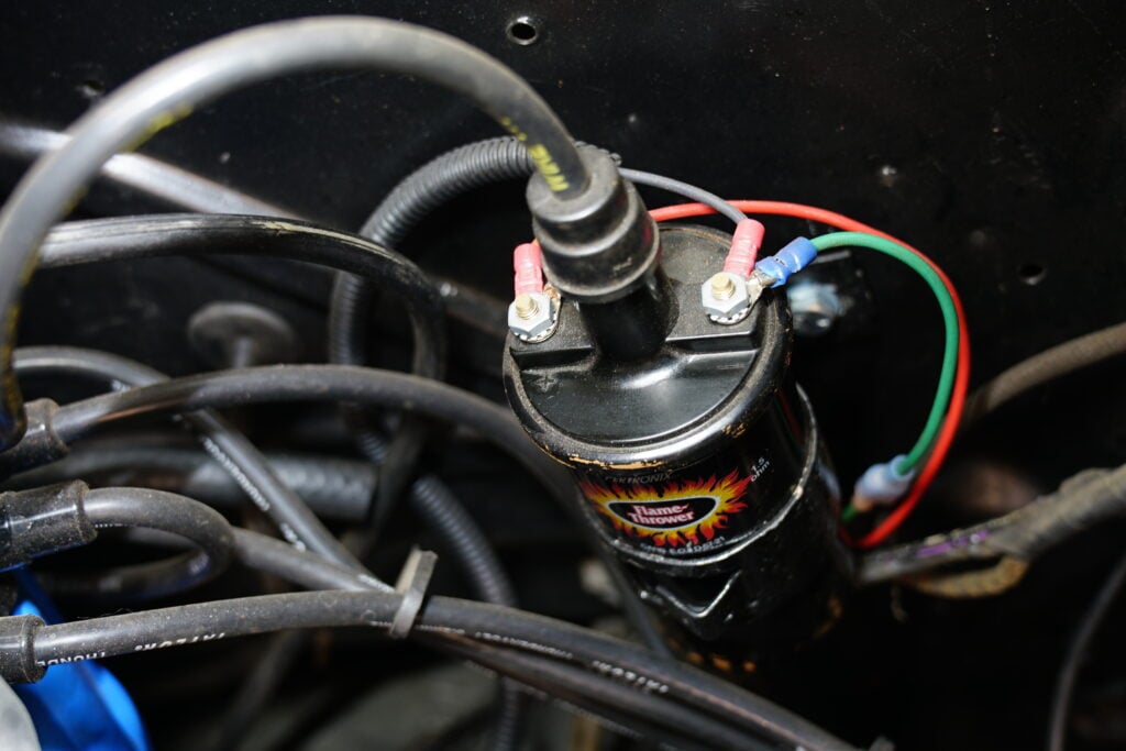
Identify the ignition coil or ignition system wire where the tachometer signal will be tapped into.
Connect the tachometer signal wire to the appropriate wire in your vehicle's wiring harness.
Establish a secure connection using wire connectors, soldering, or recommended methods.
Connect the Power and Ground Wires:
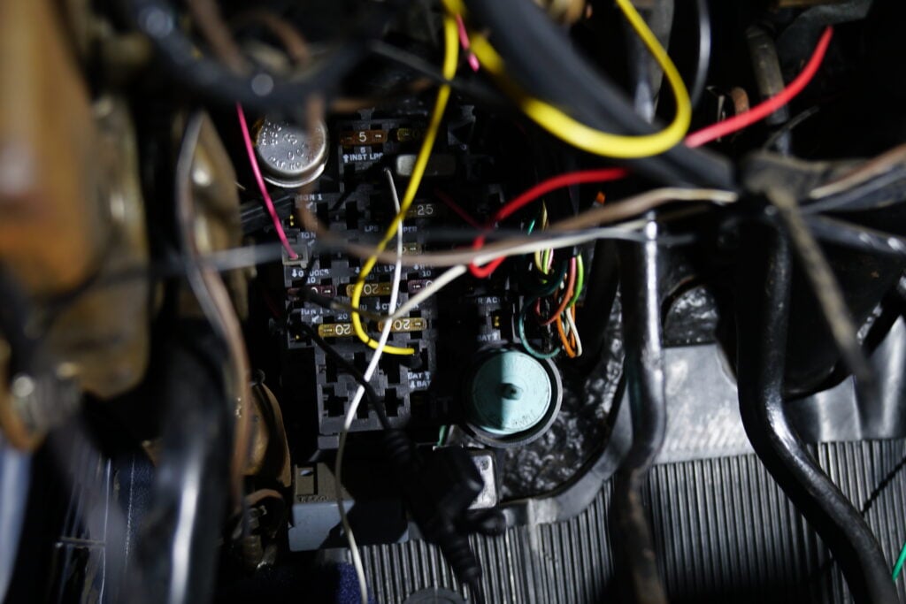
Identify a suitable power source that receives power when the ignition is on, like the fuse box or ignition switch.
Connect the tachometer's power wire to the chosen power source using an appropriate fuse or circuit protection.
Locate a suitable ground point near the tachometer mounting location.
Securely connect the tachometer's ground wire to the vehicle's metal chassis or grounding point.
Secure and Route the Wiring:
Use zip ties or other suitable methods to secure the wiring, preventing loose or dangling wires.
Carefully route the wiring to avoid interference with moving parts and maintain the driver's view.
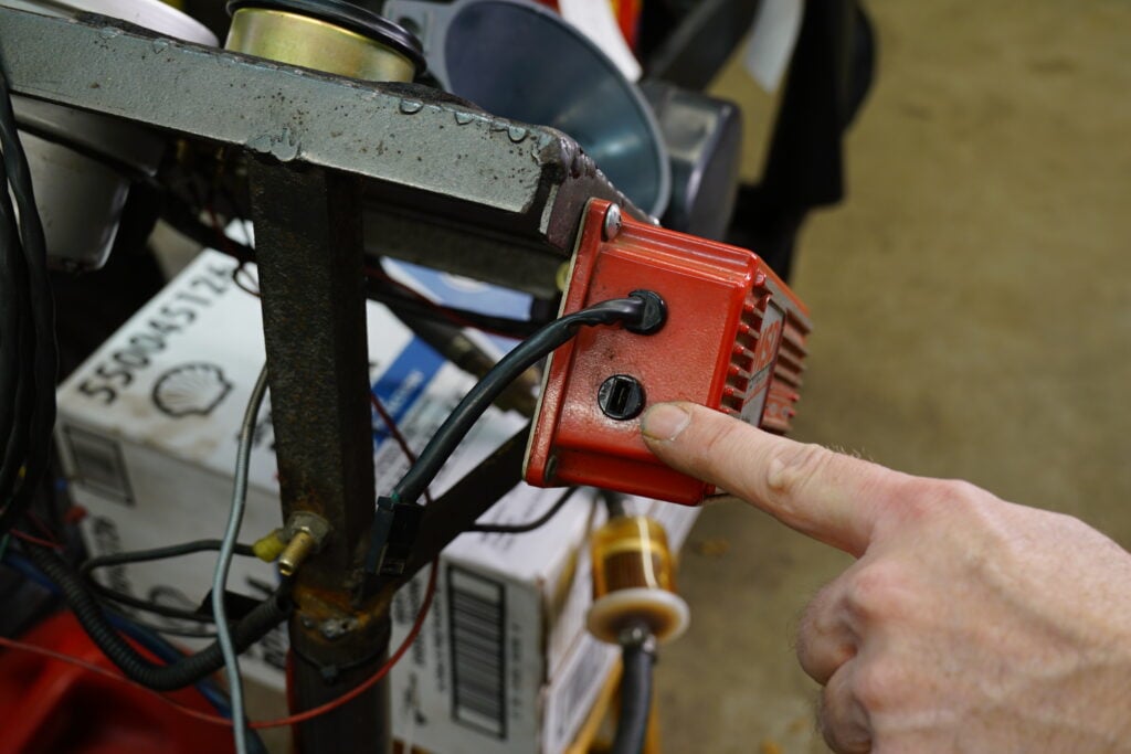
Test the Tachometer:
Start the vehicle and ensure that the tachometer functions correctly.
Observe the tachometer readings as you rev the engine to confirm accurate RPM measurements.
Finalize the Installation:
Double-check all connections, ensuring they are secure and free from loose wires.
Adjust the tachometer's mounting angle or position if necessary for optimal visibility.
Reinstall any panels or trim pieces removed during the installation process.
Test and Verify Operation:
Take your vehicle for a test drive to ensure the tachometer functions correctly under various driving conditions.
Verify that the tachometer readings align with your vehicle's RPM range and engine performance.
Please note that these instructions serve as general guidelines, and the specific installation process may vary based on your vehicle's make and model and the tachometer you are installing. Always consult the manufacturer's instructions and wiring diagrams specific to your tachometer and vehicle for a proper and successful installation.
Sign up now to join the JEGS email newsletter and be the first to learn about new products, special deals and e-mail only offers!
Tachometers typically receive their signal from specific sources such as the negative side of the ignition coil, the engine's ECM/computer, or an aftermarket ignition control box. Understanding where the tachometer gets its signal is crucial for correct installation.
Testing a tachometer's functionality involves starting the vehicle and confirming that it accurately displays RPM readings as you rev the engine. Ensuring the tachometer works correctly is essential for accurate engine performance monitoring.
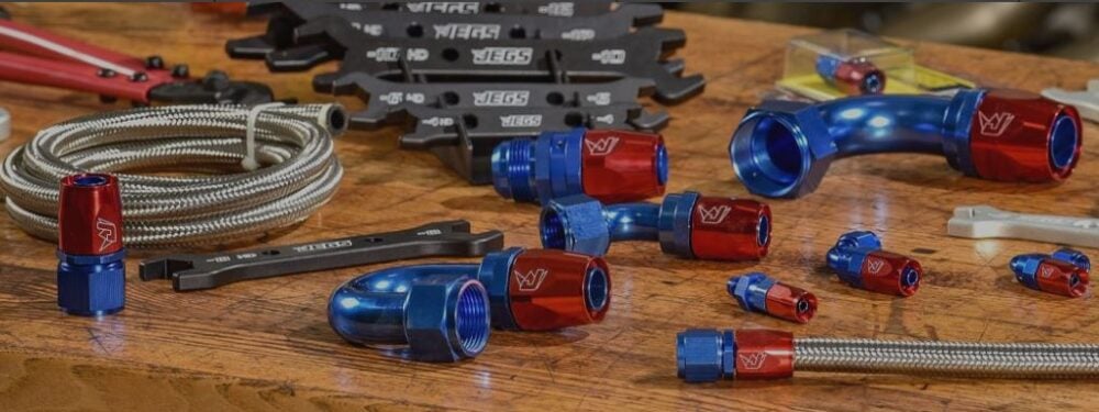
When connecting a tachometer, it's essential to use the right wiring connection. Options include soldered connections with heat shrink tubing, butt connections with crimping, quick-release connections with male and female clip ends, and twisting wires together with electrical tape or wire nuts. Choosing the appropriate connection method ensures a secure and reliable installation.
Most tachometers come with instructions that include a wiring diagram. If you don't have the instructions, you can determine your tachometer's brand and type and search online for a corresponding wiring diagram. Each brand and model may have unique wiring connections.
If you don’t have the instructions for how to install a tachometer that were included, and you are unable to contact the manufacturer for the instructions, some guesswork will be required to complete the connections (Autometer tachometer wiring, for example) and great care will have to be given so as not to damage the tachometer or the vehicle's systems and components. It is not recommended to guess as it may cause damage to the tachometer, coil, ignition box, or vehicle wiring and components, so keep this in mind if you choose to proceed further.
Hooking up a tachometer wiring harness: In most cases,
If there are any additional wires in the tachometer wiring harness, you will need to determine the manufacturer of the tach and reach out to them for proper wiring instructions. A JEGS technical support specialist can also help you with identification and installation.

Hi
I am interested in a cowl induction scoop/ or hood to be able to let the engine get cooler air,and reduce the engine compartment temp.’s .
My questions to you are . How is the induction effect achieved ,and does placing the cowl scoop close to fwd windshield increase or decrease the
effects?
Does the length,and height of the scoop play a factor in the total aerodynamic induction effects?
Does speed of vehicle count in the cowl induction?
Will this cowl scoop help to reduce engine compartment temperatures,and increase engine performance?
What happens to the air flow in the engine bay,while car is at speed ,air entering through the radiator grille,and air through the cowl scoop
will this affect the reason for having a cowl scoop?
For o.e.m. hoods ,when installing cowl scoop,do you cut only the perimeter under the scoop dimensions?
Thanks for any technical advice
Hello Spiro. This question is not related to this blog. However, we will answer it.
A cowl induction setup is more than just a visual upgrade. The idea behind it is to pull in cooler, denser air from outside the engine bay, which can help both with power and underhood temperatures. The way it works is by taking advantage of the high-pressure area that naturally forms at the base of the windshield when the vehicle is moving forward. That pressure buildup can be used to push air into the scoop and then into the intake system if it’s sealed properly. Positioning the scoop close to the windshield is important because that’s where the pressure is strongest. The shape, length, and especially the height of the scoop all influence how much air is gathered. Taller scoops can improve the effect, but they also bring more wind resistance and can affect visibility. For most street applications, something in the 2.5 to 4 inch range tends to strike a good balance.
Vehicle speed absolutely plays a role. The faster you’re going, the more pressure builds at the base of the windshield, which increases the airflow into the scoop. At lower speeds or idle, the effect is less pronounced, but the scoop can still help with venting heat if it’s designed to do so.
As for heat, yes, a properly designed cowl scoop can help reduce underhood temperatures. When the vehicle is moving, it brings in cooler outside air and can help push hot air out if your engine bay has a good exit path for it, usually down below or around the firewall. If you’re drawing in air through both the grille and the cowl scoop at the same time, you just want to be sure there’s a good outlet for that air to keep pressure from building up in the engine bay.
When it comes to installing a scoop on an OEM hood, you typically only cut the center section under the scoop to allow airflow. You don’t need to cut the entire perimeter. It’s a good idea to reinforce the hood where needed and make sure the scoop seals properly so it doesn’t let in water or rattle over time.
If you’re ready to shop for a scoop or a full cowl hood, JEGS has a wide selection in steel and fiberglass depending on your vehicle and preference. You can always give us a call at 1-800-345-4545, and a tech specialist can help you pick the right parts and make sure everything lines up with your goals. Let us know how the project goes. It sounds like a great build.
Hi Pete
For tach gauges ,non diesel style
-Is it amplitude (volts ) or waveform frequency that causes tach gauge to read rpm?
-How about current of waveform ,any effects on readings?
-Between what min. and max. signal amplitude is required by signal source?
Hi Spiro,
Great technical questions as always! For non-diesel style tachometers, the primary factor that determines the RPM reading is the waveform frequency, not amplitude or current. The tachometer measures how often pulses occur—each pulse typically representing one ignition event. So, if you’re using a signal from the coil, ignition box, or ECU, the tach gauge calculates engine speed based on the frequency of those pulses over time.
That said, signal amplitude (voltage) does matter to a point. Most tachometers require a minimum threshold voltage to recognize the signal properly—usually somewhere around 5 to 12 volts peak. Most aftermarket tachs are designed to accept a square wave or pulsed DC signal in that voltage range. If the signal is too low (under 5V), the tach might not register consistently. If it’s too high (say 20V+), it could cause erratic readings or even long-term damage if the gauge isn’t protected internally.
As for current, it’s generally minimal and doesn’t directly affect the reading. Tachometers are designed with high-impedance input circuits, so they draw only a small amount of current—just enough to detect the voltage signal and measure its frequency. The circuit isn’t measuring how much current flows, just when the pulses happen.
To summarize:
Frequency is what determines RPM.
Amplitude (voltage) needs to fall within the accepted range (typically 5V–12V for most aftermarket tachs).
Current has little to no effect on the reading.
If you’re ever in doubt or building a custom signal setup, using a tach signal adapter or signal conditioner (like the Dakota Digital SGI-100BT) can help ensure your signal is safe and accurate for the gauge. And as always, if you need help selecting components, give JEGS Tech Support a call at 1-800-345-4545. You’re asking all the right questions, Spiro—keep it up!
Hi Pete
Do all modern stepper motor technology tach. gauges use a square waveform to function?
How can one tell the signal source type for the gauge to work properly,other than asking the manufacturer?
Thanks
Hi Spiro,
Great question! While most modern stepper motor tachometers use a square wave signal, not all of them require it exclusively. Most electronic stepper motor tachometers are designed to work with a square wave signal because it provides a clean, precise, and stable RPM reading. However, some stepper motor tachs can also work with an inductive or sine wave signal, depending on their internal circuitry and compatibility. A square wave signal, or digital pulse output, is typically generated by ECUs, MSD ignition boxes, and some electronic distributors, making it the preferred signal type for most aftermarket tachometers. Examples of devices that output a square wave include the MSD 6AL, Holley Sniper EFI, and most modern digital ignition systems. On the other hand, an inductive (sine wave) signal is commonly found in older points-style ignitions, some factory distributors, and certain alternator signals. Some modern tachometers can read an inductive signal, but they may require a signal adapter. A common example of an inductive signal source is directly tapping into a coil’s negative terminal.
If you’re unsure about your signal source, you can test it using a multimeter or an oscilloscope. To use a multimeter, set it to AC voltage mode, start the engine, and probe the signal wire. If you see a fluctuating voltage (~1-12V AC), you have an inductive/sine wave signal. If the voltage switches sharply between two values (e.g., 5V or 12V), it’s a square wave. An oscilloscope provides a more precise method by allowing you to observe the waveform—square waves have clean, sharp edges, while sine waves appear smooth and rounded. Another way to determine your signal source is by checking the device providing the signal. If it comes from an MSD box, EFI system, or aftermarket ignition control, it’s likely a square wave. If it originates from a coil (-) terminal, an alternator, or a mechanical distributor, it’s likely an inductive (sine wave) signal.
If your tachometer requires a square wave, but your signal source provides a sine wave, you’ll need a tach signal adapter. Common signal adapters include the MSD 8920 Tach Adapter for older ignition systems and the Holley 554-130 Tach Adapter for EFI conversions. Most modern stepper motor tachometers use a square wave signal, but some may accept sine wave inputs. If you need help finding the right tachometer or signal adapter, feel free to call JEGS Tech Support at 1-800-345-4545. Hope this helps, and good luck with your setup, Spiro!
Spiro,
Regarding your question, “If a standard tach gauge is rated to work off a signal from the coil neg.,and also square waveform.
-What would happen if said gauge received signal from R term. alternator?
-Will this non diesel tach. gauge need an adapter to work properly? ”
If a standard tach gauge is designed to work off a coil negative signal or a square waveform signal, connecting it to the R terminal of an alternator can cause issues without an adapter. Here’s why:
The R terminal on an alternator outputs a pulse signal proportional to alternator RPM, but it’s usually an AC sine wave signal, not the square wave or clean DC pulse your tach expects. This can lead to:
Inaccurate RPM Readings:
Since the R terminal signal is an AC sine wave, the tachometer might display erratic or incorrect RPM readings.
Some tachs designed to read a square wave may not register the signal at all or could show fluctuating or bouncing RPMs.
Signal Voltage Mismatch:
The R terminal typically outputs a lower voltage AC signal compared to the higher voltage pulses from a coil negative terminal or an ECU.
If the signal voltage is too low, the tach might not detect it consistently.
Will You Need an Adapter for a Non-Diesel Tach Gauge?
Yes, you’ll likely need a signal adapter to convert the AC sine wave signal from the R terminal into a clean square wave signal that your tachometer can read accurately.
Recommended Signal Adapters for Your Setup
To make your tach work correctly with the alternator’s R terminal, consider using one of these adapters:
MSD 8920 Tach Adapter (available at JEGS):
Designed to convert various signal types to a form that most tachs can read.
Works well if your tachometer expects a coil negative or square wave signal.
AutoMeter Tach Adapter (available at JEGS through search):
Specifically built to convert signals for AutoMeter tachs but can work with other brands.
Ensures accurate RPM readings from alternator or coil sources.
If you need help finding the right adapter, feel free to call JEGS Tech Support at 1-800-345-4545. They can recommend the best option for your tach setup. Hope this helps, Spiro, and good luck with your project!
Hi Spiro, in regard to your question, “What could happen to a tach gauge that is only meant for square wave form if using an alternator signal source?
Is it the worst case ,that it won’t read the signal, but no damage to gauge?”
If a tachometer that is designed only for a square waveform signal is connected to an alternator signal source, the worst-case scenario is that it simply won’t read the signal correctly—but it is unlikely to cause permanent damage to the gauge. The reason for this is that most modern stepper motor tachometers are built to interpret a clean, consistent digital square wave signal from an ignition system, such as an ECU, ignition box (like MSD 6AL), or coil negative terminal. On the other hand, an alternator signal (R terminal) outputs an AC sine wave signal, which varies in frequency and amplitude based on alternator speed, not engine RPM. Since your tach is not designed to process this fluctuating AC voltage, a few things could happen:
No RPM reading at all – The tachometer may not recognize the signal and stay at zero.
Erratic needle movement – The tach may display inconsistent or jumping RPM readings because the alternator’s frequency doesn’t match what the tach expects.
Incorrect RPM values – If the tach does pick up a reading, it may be inaccurate because alternator speed doesn’t always correlate exactly to engine RPM.
Will It Damage the Tachometer?
In most cases, no permanent damage will occur because the input circuit on a tach is designed to filter out incorrect signals rather than overload the electronics. However, if the alternator’s output voltage spikes too high, it could cause electrical stress on the tach’s input components over time.
How to Make It Work?
If you need to run a tach off an alternator signal, you’d want to use a tach signal adapter, such as:
Dakota Digital SGI-100BT – Converts various signal types (including alternator R terminal) to a usable square wave.
MSD 8920 Tach Adapter – Designed for ignition signal conversion but may help depending on the tach.
Final Recommendation
If your tach only accepts a square wave signal, it’s best to use a proper ignition-based RPM signal rather than trying to pull it from the alternator. If you need help finding the right adapter or tachometer for your setup, feel free to call JEGS Tech Support at 1-800-345-4545.
Hi Jegs
Can one run 2 separate tach gauges from a single msd 6al box?
If so, Do the tach gauges have to be exactly identical in performance and electrical specs. ?
Thanks!!
Hi Spiro,
Yes, you can run two separate tachometers from a single MSD 6AL box, but there are a few important things to consider to ensure they function correctly.
The MSD 6AL has a dedicated tach output terminal that provides a clean tach signal.
This terminal can typically handle two tachs, but the setup needs to be done correctly.
Some tachometers may require an MSD Tach Adapter (MSD 8920 or MSD 8910) to work properly.
If one or both tachs are not reading correctly, you may need to install an adapter.
Do the Tachs Have to Be Identical? No, they do not have to be identical, but it helps if they have similar electrical characteristics.
Some tachometers have different internal resistance or signal filtering, which can cause one to behave differently than the other.
Wiring Considerations:
Ideally, both tachs should be wired in parallel from the tach output terminal.
If there are signal issues, try using a Y-splitter or a relay to prevent interference.
Alternative Option: MSD Tach Signal Splitter
If you run into signal issues, MSD offers a Tach Signal Splitter, which ensures both tachs receive a consistent and stable signal.
Yes, you can run two tachs from the MSD 6AL.
They don’t have to be identical, but they should have similar electrical requirements.
Use the MSD tach output terminal, and if there are signal issues, consider an MSD tach adapter or signal splitter.
If you need further assistance, contact JEGS Tech Support at 1-800-345-4545. Good luck with your setup!
“Thanks for the technical advice regarding dual tach gauge setup with MSD ignition.
I was wondering if you might be able to answer this tech.’l question (a bit unusual).
I need to set up a tach gauge that is able to read the alternator rpm,yes,alternator rpm
during racing.
Do I need to get a tach signal from the alternator R terminal,and via an adapter convert this
signal to reflect the alternator rpm?
I know that Dakota Digital has such a device SGI-100BT electronic controller.
Can I use this device to receive the second tach signal from the MSD box as you described in your email,
and run the second tach gauge,again to reflect the rpm of the alternator ?
Can this device cause any issues with the MSD box already driving a tach. gauge due to any impedance resistance ?
Unusual to say the least ,but I guess maybe doable?
Thanks again!”
Hi Spiro,
That’s a great (and unique) question! Setting up a tachometer to read alternator RPM during racing is definitely doable, but you need to convert the alternator’s signal properly to work with a tach gauge. Let’s break this down:
How to Read Alternator RPM on a Tachometer
Using the Alternator “R” Terminal:
Yes, you can use the R terminal (or “Stator” terminal) of the alternator to generate an RPM signal.
However, the frequency of this signal is directly tied to the number of poles in the alternator and the pulley ratio between the crankshaft and alternator.
Signal Conditioning – Dakota Digital SGI-100BT:
The Dakota Digital SGI-100BT is a tach signal interface that can take an alternator’s stator (R-terminal) output and convert it into a tach signal for a gauge.
This device allows for calibration based on alternator pulley size and engine RPM, so you can dial in an accurate alternator RPM reading.
Can the SGI-100BT Also Receive the Second Tach Signal from the MSD Box?
The SGI-100BT can accept multiple signal sources and modify them.
You could use one channel for the MSD tach signal (for the engine tach) and another input from the alternator’s R-terminal to drive the second tach.
You’d need to program the SGI-100BT so it properly scales the alternator RPM relative to engine speed.
Will This Interfere with the MSD Box’s Tach Output?
No, it shouldn’t cause any issues with the MSD box already driving a tach gauge.
However, impedance mismatches could arise if multiple devices are drawing from the MSD tach output.
If interference occurs, consider using an MSD Tach Adapter (MSD 8920) to isolate the MSD tach signal from the alternator signal.
Final Setup Recommendation
First Tach (Engine RPM) Setup:
Connect MSD 6AL tach output directly to your primary tach gauge.
If necessary, use an MSD 8920 adapter to ensure a clean signal.
Second Tach (Alternator RPM) Setup:
Connect the alternator R-terminal output to the Dakota Digital SGI-100BT.
Use the SGI-100BT output to drive the second tachometer.
Calibrate the SGI-100BT based on your alternator pulley ratio.
Possible Adjustments for Accuracy:
If the alternator pulley is smaller than the crank pulley, the alternator spins faster than engine RPM.
Adjust the scaling factor in the SGI-100BT so the second tach reflects true alternator RPM.
Summary – Is It Doable?
Yes! Using the Dakota Digital SGI-100BT, you can convert the alternator’s signal into a readable tach signal. This setup shouldn’t interfere with your MSD ignition, as long as each tach signal is properly isolated and calibrated.
If you need further assistance, feel free to call JEGS Tech Support at 1-800-345-4545. Best of luck with your racing setup—this sounds like a cool project!
Leave a Reply